The Narcissus, in a promotional advertisement by the Miller
Trolley Shoe Company in Boston, MA. Circa 1917,
featuring the new technological advancement
highlighted in the circle in the top left of the image.
The innovative trolley "shoe," with a replaceable carbon
insert, that was used in place of the brass trolley wheel to conduct
electricity for operating the high-speed, luxury interurbans
of the Portland-Lewiston Interurban.
Photo in the O. R. Cummings Collection
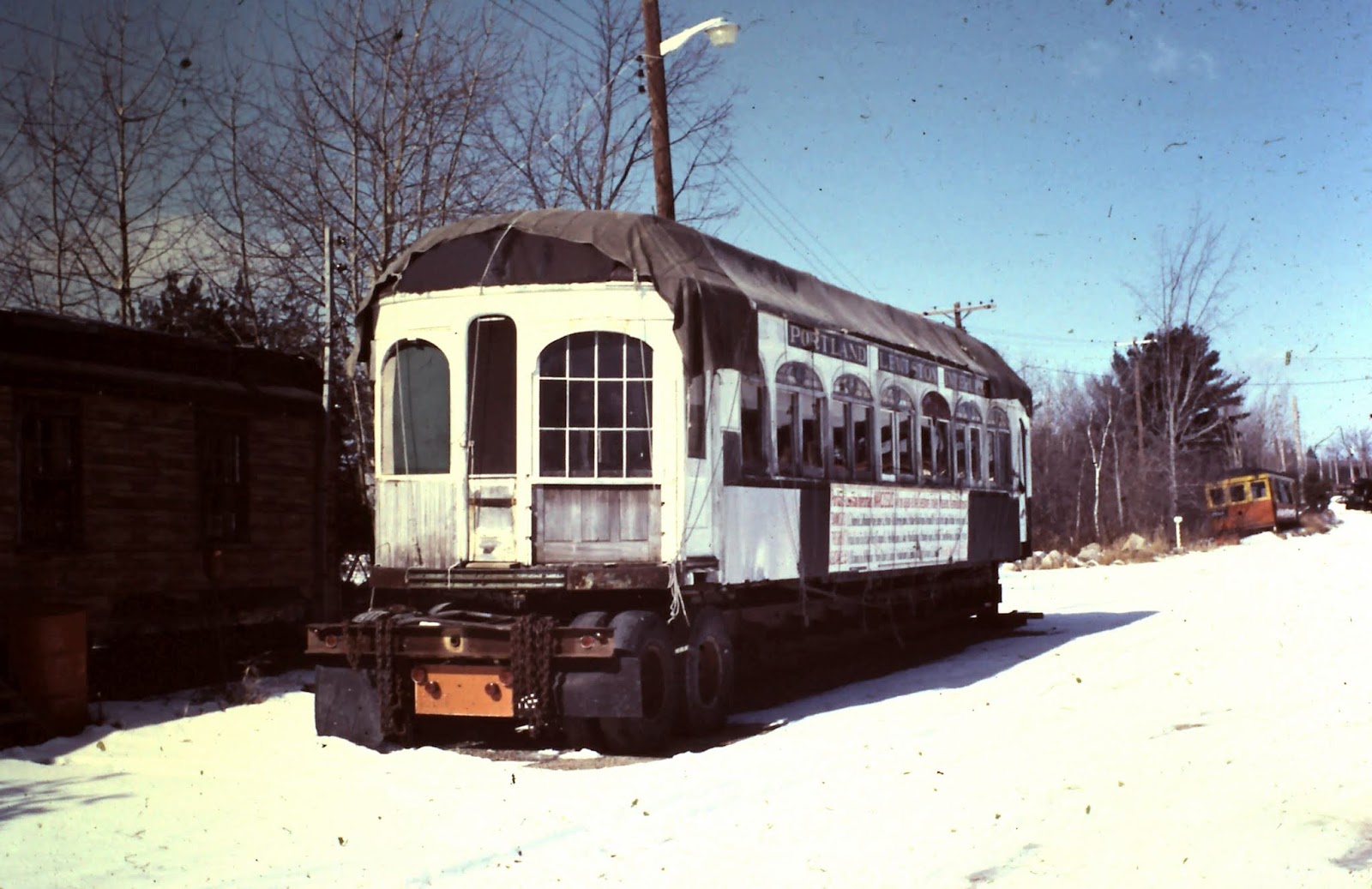
The Narcissus was built in 1912 in Laconia, NH, and operated on the Portland-Lewiston Interurban (PLI) between the two cities from 1914 to 1933. Theodore Roosevelt was a passenger on the Narcissus from Lewiston to Portland on August 18, 1914.
The Narcissus1912 blog posts include updates on the restoration of the National Register of Historic Places, Narcissus, which is currently taking place at Seashore Trolley Museum's Donald G. Curry Town House Restoration Shop in Kennebunkport, Maine. Posts also include topics; on the connections that Theodore Roosevelt has here in Maine, the PLI and its connections to the communities it served (Portland, Falmouth, Cumberland, Gray, New Gloucester, Auburn, and Lewiston), the builder of the PLI, W. S. Libbey, other electric railway systems in Maine, and people of Maine that had an impact on the electric railway development here in Maine.
Restoring historic electric railway transportation vehicles is challenging, expensive, and can take many, many years. With a project like the historic Narcissus, retired from public service in 1933, stripped of all original mechanical and electrical components, with its body serving as the Vallee family summer camp for 35 years. takes the work to complete the restoration to a higher level, full of challenges. Animated, virtual 3-D technology has become a critical ally in helping overcome some of the inherent challenges.
This restoration update focuses on the work associated with the "Body Truss Rods." The details of the various steps involved, working on trusses, and the associated components, as reported by Ernie Eaton.
Ernie is one of the restoration shop staff members. He is the project manager of the Narcissus, overseeing all aspects of the restoration work involving the Narcissus. He, with other restoration shop staff and volunteers moving the Narcissus restoration project forward.
First, some information on what the truss rods are, some of the associated components, where they are located on the Narcissus, and how virtual 3-D CAD software by Solidworks is used to help with the restoration work. Then, into the details of the truss work.
Definitions: From the 1911 publication, Electric Railway Dictionary 1911
Body Truss Rod
A round iron or steel rod from 1 in. to 1 1/2 in. in diameter that extends from end to end of the car under the longitudinal sills. It is anchored near the ends of the longitudinal sills or to the end sills and passes over the bolsters and under the queen posts dropped from the needle beams. It thus forms a shallow truss with the longitudinal sill above it and materially stiffens the underframe against sagging in its central section. Two to four truss rods are used under long interurban cars and many double-truck city cars of only moderate length. (See Overhang Truss Rod.)
.jpg)
The red circles indicate where the ends of the body truss rod are anchored on the base
of the sidesill, where the bolsters and the body truss rod saddle connect. The yellow
circles indicate where the body truss rod queen posts drop down from the needlebeam
and attach to the body truss rod. The green circle indicates where the body truss rod
turnbuckle connects the threaded interior ends of the body truss rod.
Photo in the O. R. Cummings Collection
Body Truss Anchor
A casting bolted to the underside of the side sills at or outside of the bolsters to which the ends of the body truss rod are secured. The truss rod is sometimes carried on a saddle on top of the bolster and extends through the end sill, where it is fastened with a large nut and washer on the outside face.
Body Truss Rod Queen Post
A strut dropped from the needlebeam against which the body truss rod bears.
Body Truss Rod Saddle
A bearing for a continuous body truss rod on top of the body bolsters.
Body Truss Rod Turnbuckle
A turnbuckle is used to tighten up the body truss rods. Inserted at or near the central section of the car.
Needlebeam
A cross member of the underframe between the bolsters. Two such beams are usually used, and the body truss rod queen posts are dropped from them. The terms cross frame tie, cross bearer, cross tie, cross tie timber, and body transom are all applied to this piece, but the term needlebeam, which is borrowed from bridge engineering, while not truly descriptive, is accurate and distinctive.

Closeup

The two original body truss rod turnbuckles from
the Narcissus. Both are totally cleaned up and ready when it's
their turn to be reinstalled. EE photo

The above image of the Narcissus is a screenshot of the 3-D
virtual model generated from the digital
files uploaded to the SolidWorks software. As Ernie creates more
digital files of components and parts, the files are uploaded, and
the more complete the digital model of the Narcissus will become. EE

Screenshot EE

A screenshot still, is taken from the short virtual tour video of the Narcissus,
created by the Narcissus Project Manager, Ernie Eaton. The SolidWorks,
3-D software has been an important tool in the restoration of the Narcissus.
See the short, 3-D tour of the Narcissus: Click Here (from 2020). Screenshot EE
The virtual tour video is rendered from the SolidWorks software, made up of files of the various individual components that have been speced out and uploaded. Files upon files. Layers of files. A work in progress. As files of more components are added and specs verified, the "Narcissus" model becomes more complete.

Screenshot EE
Using the SolidWorks virtual 3-D model for working on the overhang truss rods on each side.

The overhang truss rod (see the blue rendition in the screenshot of the virtual 3-D image).
It is another challenging project within the restoration of the Narcissus passenger
compartment. Screenshot EE
Overhang Truss Rod
An inverted body truss rod is occasionally used on long cars to support the overhanging ends of the car body. It consists of an iron strap framed into the side posts just below or alongside the belt rail and extends parallel to the side sill between the bolsters. It is supported by struts or queen posts over the bolsters and is bent downward beyond them to attach to anchors on the side or end sills. Also called the overhang brace rod.
Overhang Truss Rod Anchor
A strap or cast washer is used to secure an overhang truss rod to the side or end sill.
Overhang Truss Rod Strut
A strut supporting an overhand truss rod on top of the body bolster. In some types of construction, it is formed in the shape of a bent knee.
.jpg)
The blue-colored overhang truss rod is seen in the screenshot of the virtual 3-D model
of the Narcissus. The red circles indicate where the ends of the overhang truss rod
anchor to the bottom of the side sill. The truss rod literally passes through the side sill.
The yellow circles indicate where each overhang truss rod strut is located in the
interior of the exterior wall of the passenger compartment of the Narcissus.
Screenshot EE
.jpg)
Closeup


At least one of the overhang truss rod anchors
was broken beyond repair. A new replacement was cast - PWM

Separating these is a difficult task - PWM
A couple of photos of the two types of trusses that followed by Ernie Eaton's report on the work that followed.

Original body truss rods of the Narcissus and related components
Once the work is completed, it can then be used to help align
the necessary cuts/holes in the side sills. The opposite ends are threaded.
The threaded end of the body truss rod turnbuckle is attached. Ernie Eaton photo

The ends of the body truss rods at the bottom of the image
are called anchor ends. The other ends are threaded. A body truss
rod turnbuckle is threaded onto the ends. Ernie Eaton photo

One of several square-headed bolts
removed once the body structure was raised
high enough so the bolts were accessible.
Ernie Eaton photo
PLI Car No. 14 - Narcissus
Upper Truss Repairs
Ernie Eaton
Revision June 1, 2024
All photos/drawings are by Ernie Eaton
The upper trusses (Overhang Truss Rods) are comprised of a one-half inch, by 2" flat bar that passes through notches in the window posts and rests on cast iron towers (Overhang Truss Rod Struts) above each car bolster end. The bar stock is bent at a 150-degree angle and ends about 30" from the bend. (A) 1 1/8" round bar is forge-welded to the bar stock. This round rod passes through the holes in the wood side sill, and a cast iron anchor casting that applies the lifting force to the underside of the wood sill. The end of each rod is threaded, and a nut is used to adjust truss tension. The entire assembly is approximately 424 inches (35 ft. 4 inches) long. This truss assembly is used to transfer some of the weight from each compartment end to the bolsters. The bolsters are, in turn, supported by the trucks.

35' Overhang Truss Rod
Condition
The ends of the round rod in the area that passes through the wood sill were badly rusted. Nuts were rusted in place and could not be removed without heating.

Left - painted square nut of one overhang truss rod anchor. Right - metal truss rod with severe rust visible where it passed through the wood side sill
The shape of the truss and the angle of the holes that pass through the wood side sill trap it in place. We opted to cut the round rod at a place that could eventually be repaired by welding. Once freed from the sill, the round rods were heated and the nuts removed. At some point in the past, before cutting the rods, someone cut one of the nuts apart to facilitate its removal. During its life at Sabattus Lake, a shed-like addition was added to the No. 1 left side just aft of the smoking compartment. The truss's flat bar, which is let into the exterior wall just below the window sill, was cut at each end of the opening into the shed and removed. At some point at STM, a replacement steel flat bar was fitted and welded in place. This bar was then cut once again at one of the welds by someone during the sill disassembly.
Wrought Iron
Several years ago, I bend-tested a vertical tie bolt that I had welded. The boundary between the old metal and the weld was brittle, and it broke easily without bending the surrounding metal. We then had various metal components chemically tested and discovered that I-beams and C-channels were steel, but the trusses and the tie bolts were wrought iron. This led us to assume that the upper truss bar (Overhang Truss Rod) was not repairable or would require brazed reinforcements at repairs. The Museum purchased a TIG welder at the end of last year (2023), and I decided to verify if the upper truss (Overhang Truss Rod) was weldable.
Weld Tests
A section of the original square bar and the newer steel from the previously repaired area was next cut free and then bend-tested using the hydraulic press in the metal shop. This weld broke easily with little movement of the force pressure gauge or bending of the base metal. The weld had been applied to the exposed surfaces of the bar pieces with no apparent chamfer, resulting in very little penetration and a significant portion of the joint cross-section remaining unfused. The weld tore the surface of the wrought iron away from the bar when it fractured.

Left - Original truss bar material showing where the weld tore away from the
base metal when the bending force was applied. Right - Replacement bar with
weld still attached, but did not penetrate through the full cross-section. was applied.
A test weld of the original flat bar and the new A-36 grade material was performed. Some experimentation with a test sample resulted in porosity when mild steel filler was used (ER70-S6). Cracking, when thin welds, with stainless 309L filler, was then used. Preheating and more careful, thicker welds with stainless, paying attention to slowly ramping up and down the heat, and extra fill at the end of each weld, which produced better results. During the first passes of welding on the wrought iron faces variations in the arc occurred, occasionally presumable, indicating impurities in the material. The weld puddle would take longer to wet out when this occurred.
For the test weld, the material was preheated to 300-400 degrees, then TIG welded with 309 L stainless filler rod. Interpass temperatures were kept to less than 600 degrees. The weld was then tested in the press using the previously described process, and resulted in all three materials (original wrought, weld zone, and A36) yielding/bending with no apparent cracking.

Three materials: original wrought, weld zone, and A36 - yielding/bending with no apparent cracking

Round rod test repairs were also tested with similar results
Flat Bar Repair
The left side upper truss assembly (Overhang Truss Rod) was cut through the original metal next to welds that were done during earlier restoration work. A new appropriate length section of A-36 grade 2x1/2" bar was welded in place to restore the truss' flat bar section.

The red circled area is where the weld repair was done above
and also in the close-up below

Round Rod Sections
Replacement round rods with threaded ends were fabricated. These rods are 1 1/8" in diameter, yet the ends have 1 1/4" threads. Two possible fabrication methods could have permitted this. A blacksmithing process called "upsetting" can be used to increase the diameter of a bar while reducing its length. The bar is heated to a plastic state in an area to be expanded and then stuck on either end (which need not be heated). This would have allowed the blacksmith to create a section of the rod that was 1 1/4" in diameter. Alternatively, a thread rolling (vs cutting) process could have been used. As the thread rollers are forced into the rod's surface, the displaced metal expands outward to form a portion of the threads. Based on data available for manufacturing 1" threads, the required material to produce 1 1/4" threads would be approximately 1 1/8" in diameter. My assumption is that the upper truss threads were roll-formed, although the lower truss rods, which have 1 1/2" threads, appear to have been cut. Rolling requires special hardware, and currently available tools seem limited to producing a maximum of 1" diameter threads.

We opted to build up the threaded area by welding and then turn the area (to be) round and then, "single-point," thread them on a lathe. The MIG process was used with ER70-S6 wire to do the initial build-up, with the rod preheated to about 400 degrees.

The welded area was then annealed by heating until it glowed red, then slow-cooling it in a bucket of wood ash. We believe that without this step, the weld material would have been hard in areas, making threading difficult. The heated rod is first immersed in a bucket of wood ash, which acts as a non-flammable insulator.
This slows the cooling of the metal, which leaves it annealed.
The shafts were then rough-turned to reveal any under-filled areas. These areas were then filled using the TIG welding process. MIG was used because of its high deposition rate. While we could have done two layers of welds to ensure sufficient coverage, it was quicker and less costly to touch up low spots. TIG was used for this because it is easier to match the surrounding area without excessive buildup, which would have increased the subsequent lathe-turning time. The part was once again annealed after the weld touch-up. They were then turned to a finished size and threaded on the lathe.

Left - volunteer, Kevin Dyer, machining threads on a rod.

Once threaded, the rods are cut to the proper length for the intended location. The original ends measured 64 1/2." The length to the middle of the flat bar bend. The blacksmith had punched a mark to locate the bend point, making this measurement easier. The replacements were cut to produce a finished length about 1/2" longer. The originals appear to have been cut flush with the top of the installed nuts, and we plan to do the same. The original and new round road material was then ground to a 30-degree bevel to facilitate welding. A jig was made from an angle bar and a flat bar to facilitate clamping, and the repair was welded using the TIG process tested previously.
Only one round rod repair was welded to each truss assembly. The repaired truss end will be installed into the wood side sill, then the truss will be fitted into place on the car. We will locate and weld the opposite end repair with everything in its final location.

Truss Adjustment Nuts
Three of the nuts were in generally good condition, with some missing metal from corrosion where the nut flats came in contact with the anchor castings. Newly manufactured nuts have smaller external dimensions and a different appearance. We chose to refurbish the originals. The original lower truss' nuts were sandblasted. The threads were cleaned using a threading tap. Areas with significant corrosion were TIG brazed with silicon bronze and ground flat using a handheld angle grinder. Each nut was then installed onto one of the threaded replacement rods still in the lathe and machined to form a clean surface perpendicular to the threaded hole. The nut that had been cut through required more brazing. The middle image below, showing the machined face, reveals the larger area repaired on the nut that had been cut. The same TIG brazing process was used, and what brass bled through the cut into the threads was cleaned up with a tap.


This was our first use of the TIG brazing process, and it was quite effective given the ability to control the shape of the brass buildup.

A fabricated round-rod repair section is welded onto the original truss assembly

~~~~~~~~~~~~~~~
Click Here: For the list of links to Theodore Roosevelt Maine Heritage Trail Posts in Easy Order to View
We continue the restoration work on the 1912 Narcissus, the only surviving high-speed, luxury interurban coach of the Portland-Lewiston Interurban.
Click Here: Narcissus Restoration-Related Posts
Being more than a century old, the stately, "Elegant Ride," Narcissus, is a gem. This shimmering precious stone of Maine transportation history is brilliantly resplendent as it emanates so many elements of history, including time, places, people, and events, that it was coupled to, that when just a smattering of its seemingly innumerable stories are shared, the contents first captivates, fascinates, then generates interest to learn more 🙋. The majestic Narcissus is listed in the National Register of Historic Places.
Please consider joining the epic journey to complete the Narcissus Project by making a donation today!
Click Here: Donation Options
The restoration of this majestic icon of Maine's electric railway history is but one in a series of captivating stories containing an abundance of incredible coalition of narratives.
Click Here: History-Related Posts - Narcissus and Portland-Lewiston Interurban
The Narcissus is featured in the national Gold Award-winning novel, Teddy Roosevelt, Millie, and the Elegant Ride. The "Elegant Ride" is the Narcissus. Theodore Roosevelt was a passenger on the Narcissus on August 18, 1914, between Lewiston and Portland, Maine, while campaigning for the Progressive Party candidates.
Click Here: Bookstores and Businesses promoting the Narcissus Project

Independent book publisher, Phil Morse, holding
the Gold Book Award Winner plaque for
Middle Reader category for The Eric
Hoffer Book Award. Congratulations to
award-winning Maine author,
Jean M. Flahive